


- 홈
- 보드
- 아두이노
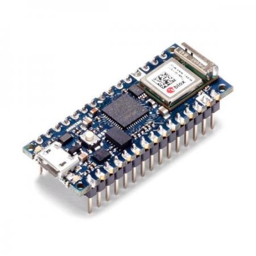
[] [Arduino Nano 33 IoT with headers] 정품 아두이노 나노 33 IoT 보드 납땜 (해외배송 가능상품)


[Arduino Nano 33 IoT with headers] 정품 아두이노 나노 33 IoT 보드 납땜 (해외배송 가능상품)
| 제조사 | Arduino |
|---|---|
| 브랜드 | Arduino |
| 판매가 | 47,700원 |
| 적립금 | 470원 |
| 자체상품코드 | P-T16 |
| 국내·해외배송 | 국내배송 |
| 배송방법 | 택배 |
| 수량 |   |
COMMENT |

 |
(최소주문수량 1개 이상 / 최대주문수량 0개 이하)
사이즈 가이드
 |
아두이노 듀에용 micro-USB 케이블 1.5m / USB A to micro B type 3,300원 |
 |
아두이노 중형 2단 멀티박스 / 다용도 멀티박스 / 부품박스 / 부품 수납 / 플라스틱 7,500원 |
 수량을 선택해주세요.
위 옵션선택 박스를 선택하시면 아래에 상품이 추가됩니다.
| 상품명 | 상품수 | 가격 |
|---|---|---|
| [Arduino Nano 33 IoT with headers] 정품 아두이노 나노 33 IoT 보드 납땜 |


|
47700 ( 470) 470)
|
|
TOTAL PRICE(수량) : 0 (0개)
|
||
이벤트
상품상세정보
Features |
|
Tech specs | |||||||||||||||||||||||||||||||||||||||||||||||||||||||||||||||||||||||||||||||||||||||||||||||||||||||||||||||||||||||||||||||||||||||||||||||||||||||||||||||||||||||||||||||||||||||||||||||||||||||||||||||||||||||||||||||||||||||||
|
This board is based on the SAMD21G18A microcontroller.
Please note: Arduino Nano 33 IoT only supports 3.3V I/Os and is NOT 5V tolerant so please make sure you are not directly connecting 5V signals to this board or it will be damaged. Also, as opposed to Arduino Nano boards that support 5V operation, the 5V pin does NOT supply voltage but is rather connected, through a jumper, to the USB power input. To avoid such risk with existing projects, where you should be able to pull out a Nano and replace it with the new Nano 33 IoT, we have the 5V pin on the header, positioned between RST and A7 that is not connected as default factory setting. This means that if you have a design that takes 5V from that pin, it won’t work immediately, as a precaution we put in place to draw your attention to the 3.3V compliance on digital and analog inputs. 5V on that pin is available only when two conditions are met: you make a solder bridge on the two pads marked as VUSB and you power the NANO 33 IoT through the USB port. If you power the board from the VIN pin, you won’t get any regulated 5V and therefore even if you do the solder bridge, nothing will come out of that 5V pin. The 3.3V, on the other hand, is always available and supports enough current to drive your sensors. Please make your designs so that sensors and actuators are driven with 3.3V and work with 3.3V digital IO levels. 5V is now an option for many modules and 3.3V is becoming the standard voltage for electronic ICs. The communication on WiFi and Bluetooth is managed by a NINA W102 ESP32 based module. The module is connected to the SAMD21 microcontoller with an SPI BUS and a serial port through the following pins:
Some of the NINA W102 pins are connected to the 15+15 pins headers/pads and can be directly driven by the module's ESP32; in this case it is necessary that the SAMD21 corresponding pins are aptly tri-stated. Below is a list of such signals:
The IMU is a LSM6DS3 and it is managed through I2C. The crypto chip is an ATECC608A and has a supporting library that is used by the WiFiNINA library. The board has a two 15 pins connectors - one on each side -, pin to pin compatible with the original Arduino Nano.
(*) As opposed to other Arduino Nano boards, pins A4 and A5 have an internal pull up and default to be used as an I2C Bus so usage as analog inputs is not recommended. Opposed to Arduino Nano boards that support 5V operation, the 5V pin does NOT supply voltage but is rather connected, through a jumper, to the USB power input. On the bottom side of the board, under the communication module, debug signals are arranged as 3x2 test pads with 100 mil pitch. Pin 1 is the bottom left one with the USB connector on the left and the test pads on the right
|
Documentatuon |
|
상품결제정보
고액결제의 경우 안전을 위해 카드사에서 확인전화를 드릴 수도 있습니다. 확인과정에서 도난 카드의 사용이나 타인 명의의 주문등 정상적인 주문이 아니라고 판단될 경우 임의로 주문을 보류 또는 취소할 수 있습니다.무통장 입금은 상품 구매 대금은 PC뱅킹, 인터넷뱅킹, 텔레뱅킹 혹은 가까운 은행에서 직접 입금하시면 됩니다.
주문시 입력한 입금자명과 실제입금자의 성명이 반드시 일치하여야 하며, 7일 이내로 입금을 하셔야 하며 입금되지 않은 주문은 자동취소 됩니다.
배송정보
- 배송 방법 : 택배
- 배송 지역 : 전국지역
- 배송 비용 : 3,000원
- 배송 기간 : 1일 ~ 2일
- 배송 안내 : - 제주도, 산간벽지나 도서지방은 별도의 추가금액을 지불하셔야 하는 경우가 있습니다.
고객님께서 주문하신 상품은 입금 확인후 배송해 드립니다. 다만, 상품종류에 따라서 상품의 배송이 다소 지연될 수 있습니다.
교환 및 반품정보
교환 및 반품이 가능한 경우- 상품을 공급 받으신 날로부터 7일이내 단, 가전제품의
경우 포장을 개봉하였거나 포장이 훼손되어 상품가치가 상실된 경우에는 교환/반품이 불가능합니다.
- 공급받으신 상품 및 용역의 내용이 표시.광고 내용과
다르거나 다르게 이행된 경우에는 공급받은 날로부터 3월이내, 그사실을 알게 된 날로부터 30일이내
교환 및 반품이 불가능한 경우
- 고객님의 책임 있는 사유로 상품등이 멸실 또는 훼손된 경우. 단, 상품의 내용을 확인하기 위하여
포장 등을 훼손한 경우는 제외
- 포장을 개봉하였거나 포장이 훼손되어 상품가치가 상실된 경우
(예 : 가전제품, 식품, 음반 등, 단 액정화면이 부착된 노트북, LCD모니터, 디지털 카메라 등의 불량화소에
따른 반품/교환은 제조사 기준에 따릅니다.)
- 고객님의 사용 또는 일부 소비에 의하여 상품의 가치가 현저히 감소한 경우 단, 화장품등의 경우 시용제품을
제공한 경우에 한 합니다.
- 시간의 경과에 의하여 재판매가 곤란할 정도로 상품등의 가치가 현저히 감소한 경우
- 복제가 가능한 상품등의 포장을 훼손한 경우
(자세한 내용은 고객만족센터 1:1 E-MAIL상담을 이용해 주시기 바랍니다.)
※ 고객님의 마음이 바뀌어 교환, 반품을 하실 경우 상품반송 비용은 고객님께서 부담하셔야 합니다.
(색상 교환, 사이즈 교환 등 포함)


 {$autoComplete_query_view}
 {$recentQuery_query}


